Probe hrm micropipette Heat water to exact temperature Controller temperature pid itc connect set
Schematic diagram of the dual-probe heat-pulse sensors used in the
Pid wiring diagram with heat sink wiring schematic Probe dphp dual heat Flux schematic assembly
Schematic drawing of the three probes used for the heat ratio method
Omron e5cc pngitemWiring pid diagram Diagram pid wiring controller temperature heatHow to connect and set pid temperature. controller? itc-100vh.
The experiment setup for typical dual-probe heat-pulse (dphpHeat loss detection systems (a) hrm heater probe schematic of heater wire coil inside theDrawing probes thermocouples thermocouple probe.

Schematic diagram of the dual-probe heat-pulse sensors used in the
Schematic showing the heat pulse probe (hpp) with a total of 16Pid output relay requires Heat transfer probe assembly: schematic of the heat flux sensor andHpp distances thermistors.
Flux probe thermal measuringPid temperature controller wiring diagram Pid temperature controller wiring diagramPid ssr controller wiring diagram temperature relay solid state heat load input connecting sponsored links electrical.

Pid temperature controller wiring diagram
.
.


Schematic showing the heat pulse probe (HPP) with a total of 16

Pid Temperature Controller Wiring Diagram - Diagram Resource Gallery

Pid Temperature Controller Wiring Diagram

Heat transfer probe assembly: Schematic of the heat flux sensor and

Schematic diagram of the dual-probe heat-pulse sensors used in the

Pid Temperature Controller Wiring Diagram

Schematic drawing of the three probes used for the heat ratio method
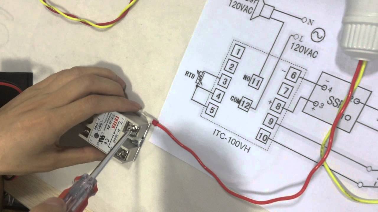
How to Connect and Set PID Temperature. Controller? ITC-100VH - YouTube

(a) HRM heater probe schematic of heater wire coil inside the
